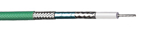
(Ex: Low Loss Coaxial Cable with a braid, foil, and a flat braid)
In environments where electrical noise is a factor. A Shielded cable is needed to prevent interference. Electromagnetic interference (EMI), whether it be radiated or conducted, can seriously disrupt the proper operation of other equipment. Jacket insulation protects a cable mechanically from scraps and abrasion and environmentally from moisture and spills, but insulation is transparent to electromagnetic energy and offers no protection. This is when shielding is needed to combat the effects of Electromagnetic interference.
In most cases, cables can be a main source of transfer for EMI, both as a source and receiver. As a source, the cable can either conduct noise to other equipment or act as an antenna radiating noise. As a receiver, the cable can pick up EMI radiated from other sources. A shield works on both.
The table below has basic rules as to the areas that are subject to these noise levels. Notice that switching heavy loads, inductive heaters, large transformers can all present high levels of both conducted and radiated EMI.
Placing signal cables next to power cables can also allow power-line noise to couple onto the signal lines.
| Noise Level |
Noise Source |
Wire Specification |
| High |
Electrolytic processes, heavy motors, generators, transformers, induction heating, relay controls, power lines and control wire in close proximity |
Heavy processing plants such as steel mills and foundries |
| Medium |
Wiring near medium-sized motors, control relays |
Average manufacturing plants |
| Low |
Wiring located far from power lines, motors; motors <5 hp; no induction heating, arcs, control or power relays nearby |
Storage areas, labs, offices and light assembly operations |
The primary way to combat EMI in cables is through the use of shielding. The shield surrounds the inner signal- or power-carrying conductors. The shield can act on EMI in two ways. First, it can reflect the energy. Second, it can pick up the noise and conduct it to ground. In either case, the EMI does not reach the conductors. In either case, some energy still passes through the shield, but it is so highly attenuated that it does not cause interference.
Cables come with various degrees of shielding and offer varying degrees of shielding effectiveness. The amount of shielding required depends on several factors, including the electrical environment in which the cable is used, the cost of the cable—why pay for more shielding than you need?—and issues like cable diameter, weight, and flexibility.
An un-shielded cable for industrial applications typically is used in a controlled environment— inside a metal cabinet or a conduit, where it is protected from ambient EMI. The metal of the enclosure shields the electronics inside.
A shield will reflect some energy, conduct some energy to ground, and pass some energy. There are two types of shielding typically used for cables: foil or braid.
- Foil shielding used a thin layer of aluminum, typically attached to a carrier such as polyester to add strength and ruggedness. It provides 100% coverage of the conductors it surrounds, which is good. It is thin, which makes it harder to work with, especially when applying a connector. Usually, rather than attempting to ground the entire shield, the drain wire is used to terminate and ground the shield. The drawback to foil is that is may not be as flexible as the braid shield.
- A braid is a woven mesh of bare, tinned copper, or silver plated copper wire strands. The braid provides a low-resistance path to ground and is much easier to termination by crimping or soldering when attaching a connector. But braided shields do not provide 100% coverage. They allow small gaps in coverage. Depending on the tightness of the weave, braids typically provide between 70% and 95% coverage. When the cable is stationary, 70% is usually sufficient. In fact, you won’t see an increase in shielding effectiveness with higher percentages of coverage. Because copper has higher conductivity than aluminum and the braid has more bulk for conducting noise, the braid is more effective as a shield. But it adds size and cost to the cable.
For very noisy environments, multiple shielding layers are often used. Most common is using both a foil and a braid. In multi-conductor cables, individual pairs are sometimes shielded with foil to provide cross-talk protection between the pairs, while the overall cable is shielded with foil, braid, or both. Cables also use two layers of foil or braid.
In practice, the purpose the shield is to conduct to ground any of the noise it has picked up. The importance of this cannot be overstated—and failure to understand the implications can mean ineffective shielding. The cable shielding and its termination must provide a low-impedance path to ground. A shielded cable that is not grounded does not work effectively. Any disruptions in the path can raise the impedance and lower the shielding effectiveness.
Practical Guidelines for Effective Shielding
- There must be the proper amount of shielding required for the application. In moderately noisy environments, a foil alone may provide adequate protection. In noisier environments, consider braids or foil-braid combinations.
- Make sure the cable fits the application, not the other way around. Mainly in situations such as robotics, cables that experience repeated flexing usually can be built with a spirally wrapped shield rather than a braid. in these situations, be sure to avoid foil shielding as the flexing could tear the foil shield.
- Confirm the equipment that the cable is connected to is properly grounded. Use an earth ground wherever possible and check the connection between the ground point and the equipment. Eliminating noise depends on a low resistance path to ground.
- Most connector designs allow full 360° termination of the shield. Make sure the connector offers shielding effectiveness equal to that of the cable. For example, many common connectors are offered with metal-coated plastic, cast zinc, or aluminum back shells. Complimenting the connector and/or cable with each other will ensure that you have proper shield performance throughout your harness or assembly.
- Ground the cable at the minimum on one end. This eliminates the potential for noise inducing ground loops. A shielded system is only as good as its weakest component. A high-quality cable is defeated by a low-quality connector. Similarly, a great connector can’t do anything to improve a poor cable.
If you have any questions please feel free to call or email us.
Phone: 775-356-8969
Email: eng@silverstatewire.com


You must be logged in to post a comment.